R2R Ladder DAC
This post is about an R2R Ladder DAC that I build one evening. I wanted to play around with the Arduino Mega 2560 board I have and this seemed like a perfect way to try it out. Below is the schematic for the DAC…
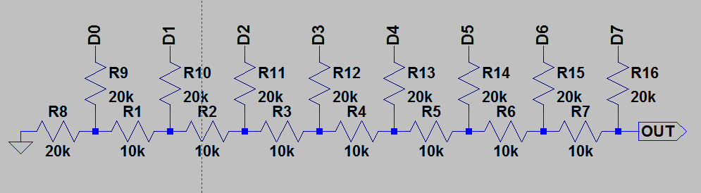
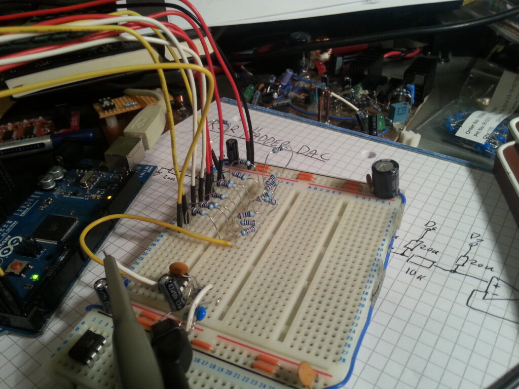
This is an 8-bit DAC built-up from just resistors, each bit is connected to a GPIO pin of the Arduino. I built the circuit on a breadboard and connected it to the Arduino using jumpers.
The first thing I did with the software is toggle the MSB bit using the Ardino digitalWrite() function, however using these functions makes writing to the DAC far too slow. So I needed to write directly to the ATmega GPIO registers and to avoid jitter I use a Timer interrupt. At the moment the software just increments PORTA each interrupt and lets it overflow, this creates a sawtooth wave on the output of the DAC and exercises each bit in the DAC.
int timer1_reload;

void setup() {
   pinMode(22, OUTPUT);
   pinMode(23, OUTPUT);
   pinMode(24, OUTPUT);
   pinMode(25, OUTPUT);
   pinMode(26, OUTPUT);
   pinMode(27, OUTPUT);
   pinMode(28, OUTPUT);
   pinMode(29, OUTPUT);
   PORTA = 0;

   noInterrupts();
   TCCR1A = 0;
   TCCR1B = 0;

   timer1_reload = 65535 - 5;
   TCNT1 = timer1_reload;
   TCCR1B |= (1 << CS10);
   TCCR1B |= (1 << CS11); // /644
   TIMSK1 |= (1 << TOIE1);
   interrupts();
}

ISR(TIMER1_OVF_vect)
{
  TCNT1 = timer1_reload;
  PORTA++;
}

void loop() {
}
Next I will generate a sine wave using the DAC.
arduino electronics