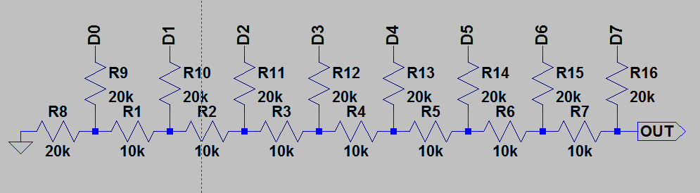
This post is about an R2R Ladder DAC that I build one evening. I wanted to play around with the Arduino Mega 2560 board I have and this seemed like a perfect way to try it out. Below is the schematic for the DAC…
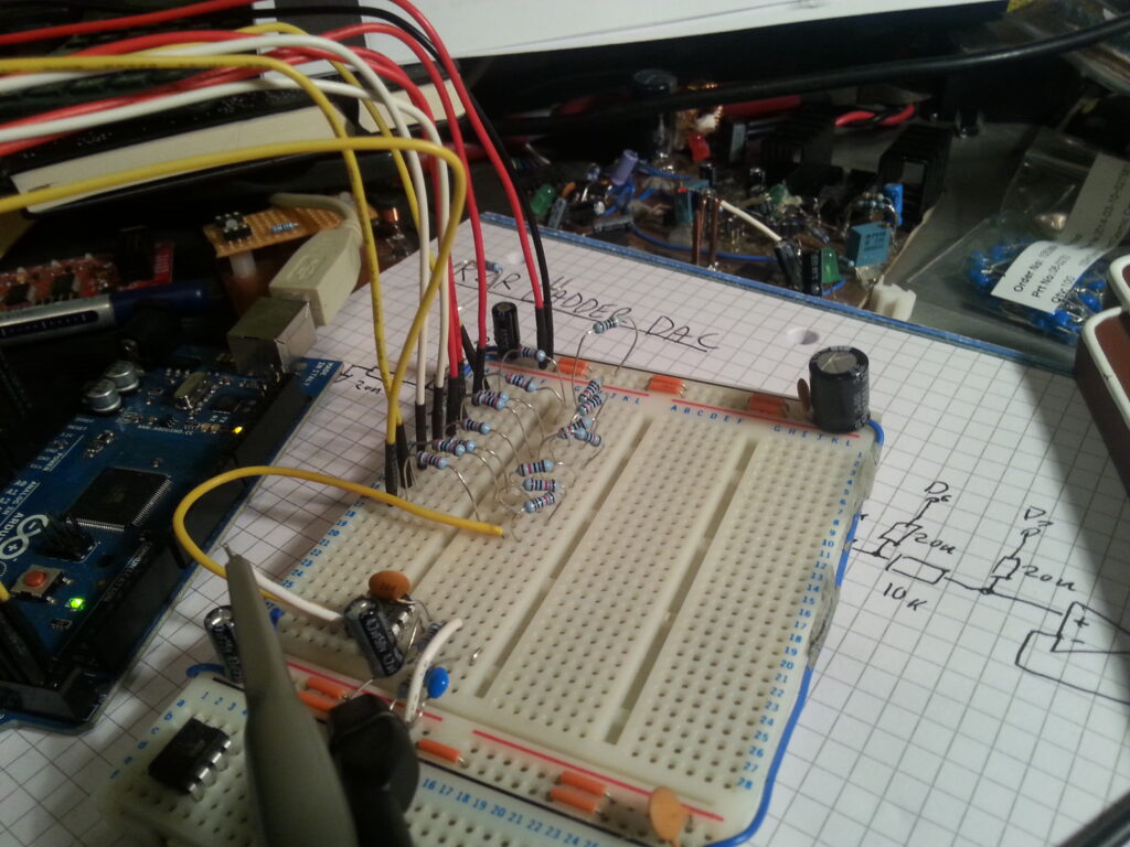
This is an 8-bit DAC built-up from just resistors, each bit is connected to a GPIO pin of the Arduino. I built the circuit on a breadboard and connected it to the Arduino using jumpers.
The first thing I did with the software is toggle the MSB bit using the Ardino digitalWrite() function, however using these functions makes writing to the DAC far too slow. So I needed to write directly to the ATmega GPIO registers and to avoid jitter I use a Timer interrupt. At the moment the software just increments PORTA each interrupt and lets it overflow, this creates a sawtooth wave on the output of the DAC and exercises each bit in the DAC.
Recently I ordered an Arduino UNO and two shields from Adafruit and two weeks ago it arrived… YAY! As soon as I signed for it I rushed to unpacked it! I was amazed at how small it is, it looked bigger in photos. So far over this couple of weeks I’ve only used a few times but those few times I have used I have been very impressed with it.
The first thing I did of course is get it flashing an LED, which only took about 10 minutes to get going. This was including the time to install the IDE on my laptop running Ubuntu 11.04. After a while I had an issue with the Ardunio IDE hanging whenever I click on the Tools menu and also an issue with the IDE reporting the serial port was locked by another application. I haven’t yet found a fix for this other than using my Fiancée’s laptop instead, which is running Windows Vista… I love cross platform software, it can be so handy sometimes.
After that I built the two shields, the first was a Protoshield with screw terminals, and the second was the data logging shield. These were both pretty easy to build and the instructions where excellent. The next thing I did was get the arduino sampling with the ADC, I did this by simply hooking a 10k pot to A0. Then I soldered an LM35 onto the data logging shield and hooked 3V3 to the VREF pin as recommended by Adafruit. At this point I was using the Serial port to get the samples out.
The next day I decided to follow the tutorials on how to use the SD card interface. Thanks to the excellent work by the authors of the various libraries this was very easy. The same for using the RTC. It all just came together and I had the Arduino sampling temperature with a timestamp to the SD card.
In conclusion I think the Arduino is fantastic and I hope to use it much more my future projects. I especially like the idea of the Arduino Pro and Nano because they can be embedded in a system somewhere.
We use cookies on our website to give you the most relevant experience by remembering your preferences and repeat visits. By clicking “Accept All”, you consent to the use of ALL the cookies. However, you may visit "Cookie Settings" to provide a controlled consent.
This website uses cookies to improve your experience while you navigate through the website. Out of these, the cookies that are categorized as necessary are stored on your browser as they are essential for the working of basic functionalities of the website. We also use third-party cookies that help us analyze and understand how you use this website. These cookies will be stored in your browser only with your consent. You also have the option to opt-out of these cookies. But opting out of some of these cookies may affect your browsing experience.
Necessary cookies are absolutely essential for the website to function properly. These cookies ensure basic functionalities and security features of the website, anonymously.
Cookie
Duration
Description
cookielawinfo-checkbox-analytics
11 months
This cookie is set by GDPR Cookie Consent plugin. The cookie is used to store the user consent for the cookies in the category "Analytics".
cookielawinfo-checkbox-functional
11 months
The cookie is set by GDPR cookie consent to record the user consent for the cookies in the category "Functional".
cookielawinfo-checkbox-necessary
11 months
This cookie is set by GDPR Cookie Consent plugin. The cookies is used to store the user consent for the cookies in the category "Necessary".
cookielawinfo-checkbox-others
11 months
This cookie is set by GDPR Cookie Consent plugin. The cookie is used to store the user consent for the cookies in the category "Other.
cookielawinfo-checkbox-performance
11 months
This cookie is set by GDPR Cookie Consent plugin. The cookie is used to store the user consent for the cookies in the category "Performance".
viewed_cookie_policy
11 months
The cookie is set by the GDPR Cookie Consent plugin and is used to store whether or not user has consented to the use of cookies. It does not store any personal data.
Functional cookies help to perform certain functionalities like sharing the content of the website on social media platforms, collect feedbacks, and other third-party features.
Performance cookies are used to understand and analyze the key performance indexes of the website which helps in delivering a better user experience for the visitors.
Analytical cookies are used to understand how visitors interact with the website. These cookies help provide information on metrics the number of visitors, bounce rate, traffic source, etc.
Advertisement cookies are used to provide visitors with relevant ads and marketing campaigns. These cookies track visitors across websites and collect information to provide customized ads.