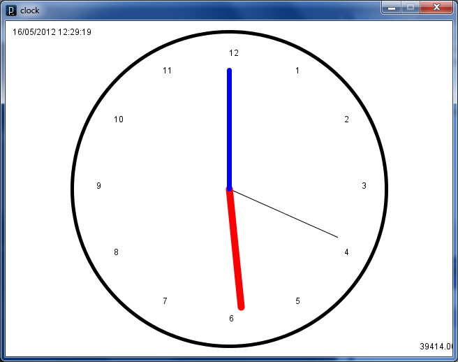
I came across some code I wrote in Processing a while ago so I thought I’d post bits of it here. I made a really simple analogue clock. Below is s screenshot of what I came up with.
I wrote a small function that handles drawing a hand of the clock. This function is called for each hand of the code by the draw loop.
void draw_hand(long count, long modulo, long len)
{
    float nx, ny;
    a = (2*PI/modulo) * count - (2*PI/4);
    nx = (width/2) + (Clock_Size/2-len) * cos(a);
    ny = (height/2) + (Clock_Size/2-len) * sin(a);
    strokeWeight(7);
    line(width/2, height/2, nx, ny);
}
Then all we need to do in the draw loop is call the function for each of the hands of the clock. Here is an example of drawing the hours hand.
To put the ticks around the outside of the clock I used the code below.
  fill(0,0,0);
  for( int i = 0; i < 12; i ++ ) {
    float angle = radians(i*30) - (2*PI/4);
    nx = (width/2) + (Clock_Size/2-35) * cos(angle);
    ny = (height/2) + (Clock_Size/2-35) * sin(angle);
    text(i == 0 ? 12 : i, nx, ny);
  }
Processing.js Version
I have got this code working fine using Processing.js. See it here
I created a macro that will generate a really simple Biconvex lens. The macro take in three arguments, Location, Radius and Overlap. It works by taking the intersection of two spheres. The resulting object is then translated to wherever you want it to go in your scene.
Last time I ran an example sketch and then wrote my own that prints “Hello World” in bright colours. Now I want to play around with some of the basic shapes that Processing provides. From the documentation it looks like the 2D primitives are the arc, ellipse, line, point, quad, rect, and triangle.
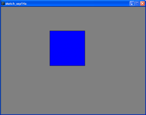
The first one I’m going to play with is the rect() primitive, so I wrote a simple sketch to draw one. All it does is set the window size then draw a rectangle somewhere in the window.
The rect() function takes four parameters as inputs, the first two are the x and y co-ordinates of where to start drawing. The second two are the height and width of the rectangle. Then I thought it would be cool if I made it follow the mouse, this as it turns out is really easy. In the draw function you get a couple of variables you can use for this, mouseX and mouseY. They hold the x and y co-ordinates of where the mouse is so all I have to do is put the call to rect() into the draw loop then use the mouse co-ordinates to set that starting position of the rectangle.
rect(mouseX, mouseY, 155, 155);
This code worked ok but the viewport filled up with loads of rectangles as you moved the mouse really quickly. I wanted just a single rectangle that followed the mouse. So I added some extra lines of code that drew another rectangle over the whole viewport to clear it then draw the smaller rectangle. I also thought it would look much nicer if the mouse cursor was always located in the centre of the rectangle rather than at the top left-hand corner. So to do this I subtracted half the width of the rectangle from the x co-ordinate or the mouse cursor, and did the same with the height and y co-ordinate. This kept the mouse cursor roughly in the middle of the rectangle.
To draw the rectangle over the entire viewport I two other special variables, width and height. These are set to the width and height of the window you are using. The code for all of this is below.
After a while playing with the Arduino I’ve become interested in Processing which is what the Arduino language and Arduino IDE is based on. Just as the Arduino is a thin layer on top of C, Processing is simply a library for Java that makes playing with computer graphics much easier. So today I’ve decided to play around with it a bit and write about it.
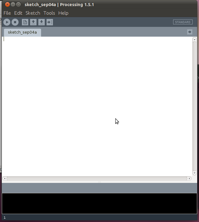
First of all I downloaded the Processing IDE from the Processing website, I downloaded the Linux version as I’m using Ubuntu but you can get a Windows or Mac OSX version as well. Then I decompressed the files and fired up the IDE by executing the “processing” file, I was then greeted by the IDE.
The Processing IDE
Looks good eh?? It looks almost idendical to the Arduino IDE. I then has a quick read through some of the documentation on the website. The first code snippet I ran was from Processing own tutorial, although I left a small bit of code out. The code for it is below, what it does is draw a circle wherever the mouse cursor currently is.
Yay, it worked!! I love how exciting it is to get instant feedback. I wasn’t sure exactly what the smooth() function did,
I suspected it may have been something to do with anti-aliasing and it turns out I was right after looking at the reference. As you can see from the screen shot it can be used to make pretty snaking patterns.
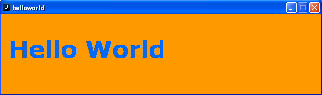
I decided that I wanted to create a sketch that printed “Hello World” because that’s the first program most people write :-). I had a quick look around the documentation on the website and I found the text() function and some example code. I typed that into the IDE but I wanted to use a bigger font, it turns out the font file must be in the /data directory of the sketch.
There is a tool provided that will take a font on your computer and turn it into something Processing can use. To use this tool, go to the “Tools” menu and select “Create Font…” and then in the dialog box that pops up select the font you want and the filename then click OK.
Clicking the run button produces a large window with “Hello World” written in large letters. It worked! Yay!!! So far it’s been pretty fun playing around with Processing, I hope to do a lot more with it. I want to use it to talk to the Arduino. Perhaps plotting the voltage on the analogue pins over time.
That’s it for now, I hope to have another post on this later in the week. See ya!
We use cookies on our website to give you the most relevant experience by remembering your preferences and repeat visits. By clicking “Accept All”, you consent to the use of ALL the cookies. However, you may visit "Cookie Settings" to provide a controlled consent.
This website uses cookies to improve your experience while you navigate through the website. Out of these, the cookies that are categorized as necessary are stored on your browser as they are essential for the working of basic functionalities of the website. We also use third-party cookies that help us analyze and understand how you use this website. These cookies will be stored in your browser only with your consent. You also have the option to opt-out of these cookies. But opting out of some of these cookies may affect your browsing experience.
Necessary cookies are absolutely essential for the website to function properly. These cookies ensure basic functionalities and security features of the website, anonymously.
Cookie
Duration
Description
cookielawinfo-checkbox-analytics
11 months
This cookie is set by GDPR Cookie Consent plugin. The cookie is used to store the user consent for the cookies in the category "Analytics".
cookielawinfo-checkbox-functional
11 months
The cookie is set by GDPR cookie consent to record the user consent for the cookies in the category "Functional".
cookielawinfo-checkbox-necessary
11 months
This cookie is set by GDPR Cookie Consent plugin. The cookies is used to store the user consent for the cookies in the category "Necessary".
cookielawinfo-checkbox-others
11 months
This cookie is set by GDPR Cookie Consent plugin. The cookie is used to store the user consent for the cookies in the category "Other.
cookielawinfo-checkbox-performance
11 months
This cookie is set by GDPR Cookie Consent plugin. The cookie is used to store the user consent for the cookies in the category "Performance".
viewed_cookie_policy
11 months
The cookie is set by the GDPR Cookie Consent plugin and is used to store whether or not user has consented to the use of cookies. It does not store any personal data.
Functional cookies help to perform certain functionalities like sharing the content of the website on social media platforms, collect feedbacks, and other third-party features.
Performance cookies are used to understand and analyze the key performance indexes of the website which helps in delivering a better user experience for the visitors.
Analytical cookies are used to understand how visitors interact with the website. These cookies help provide information on metrics the number of visitors, bounce rate, traffic source, etc.
Advertisement cookies are used to provide visitors with relevant ads and marketing campaigns. These cookies track visitors across websites and collect information to provide customized ads.