I tried to change the permissions of my ssh private/public keys in the .ssh directory under Cygwin on Windows 8 and it didn’t work. This seems to be a bug in Cygwin but there is a work around that I found through SuperUser.
chgrp -R Users ~/.ssh
Now all you need to do is run the chmod commands as usual and all should work.
I was debugging a project that used SIGUSR1 heavily, GDB stops on SIGUSR1 by default and it was making debugging a pain when I didn’t care when the signal was being generated. So here is now to set how GDB interprets signals.
By entering the following into the GDB prompt you can instruct it to not print, or stop when the signal happens and to pass it to the program.
I’ve been asked to help someone create a device that can play steam train whistle sounds when a button is pressed. I was given a load of MP4 video files with recordings of the whistles.
First I wanted to rename them because they all had a “Prj ” prefix on them. The code snippet below is what I used to remove the prefix from the file names.
for file in *.mp4 ;
do
    mv "$file" $(echo "$file" | sed 's/Prj //')
done
The next thing to do is extract the audio from all the videos. FFMPEG is perfect for this. The Bash code below will extract the audio from all of the MP4 files in a directory.
for file in *.mp4 ;
do
    ffmpeg -i $file -map 0:1 -acodec pcm_s16le -ac 2 ${file/.mp4/.wav}
done
Now that I’ve got the audio files I need to open them in Audacity and edit them, that is something I can’t automate unfortunately 😢
This is a quick guide to enabling I2C support on the Raspberry PI operating system Raspbian. This may work on the other Linux based distros available for the Pi but I have not checked.
Next we need to enable the kernel drivers for I2C, by default the drivers are blacklisted so we must un-comment the lines that include “i2c-bcm2708”
sudo nano /etc/modprobe.d/raspi-blacklist.conf
Then add the kernel module “i2c-dev” to /etc/modules
sudo nano /etc/modules
Then finally reboot the Pi
sudo reboot
Using the I2C Command Line Tools
The i2c-tools package provide a number tools for operating on the I2C bus using the command line. The first is i2cdetect which scans the bus for devices and then prints an address map.
i2cdetect -y 1
The next is i2cset, this is a tool that allows you to set register values on an I2C device. The first argument after the bus is the chip address, then the register address and finally the value to write. All of the arguments are in decimal.
i2cset -y 1 <chip> <addr> <value>
The opposite to the set command is i2cget, this reads a register on an I2C device.
i2cget -y 1 <chip> <addr>
Another tool is i2cdump which reads out all of the registers of a I2C device.
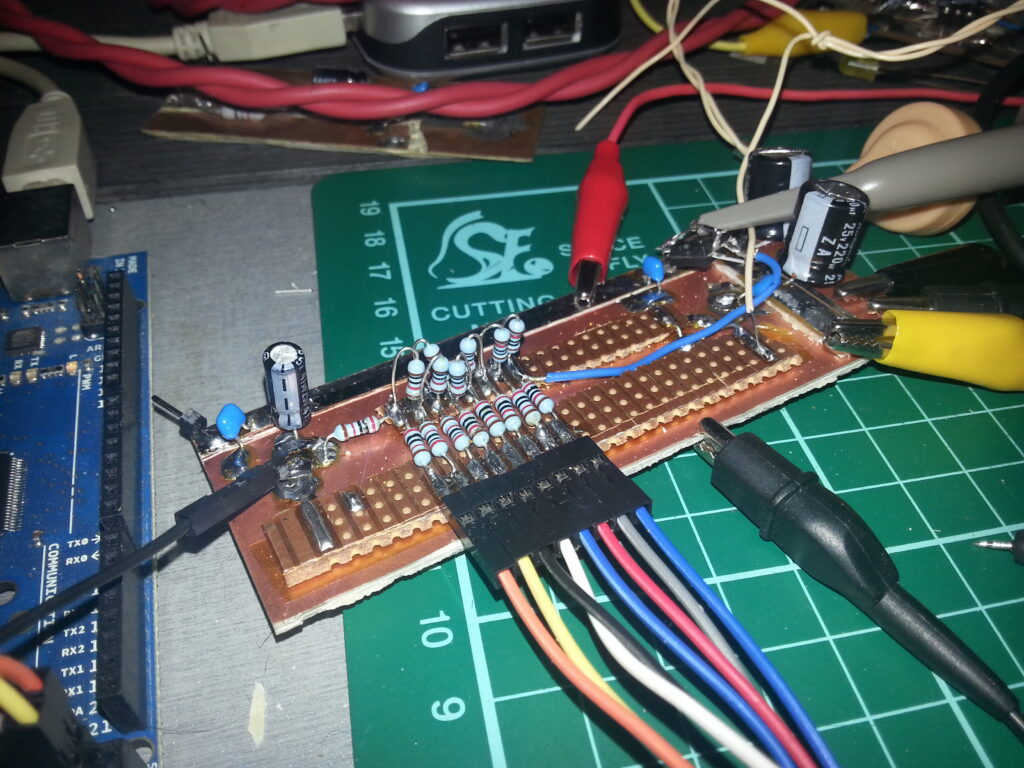
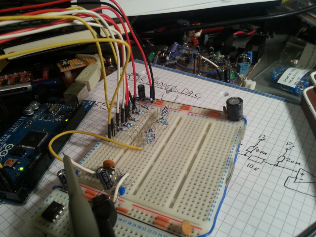
I have built the R2R ladder DAC, that I had previously built on breadboard, on a piece of copper clad board. This has fixed something that I forgot to mention in the last post; which was that at the lower end of the sawtooth ramp there was a high frequency oscillation. This was probably because of the poor grounding I had when testing. In the right-hand corner of the board I built a op-amp buffer stage.
photo of the prototype R2R ladder DAC
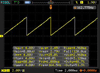
Below is a screenshot from my Oscilloscope of the DAC in operation. As you can see it works!
oscilloscope screenshot showing the sawtooth wave generated by the R2R ladder DAC
electronics
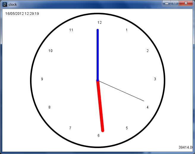
I came across some code I wrote in Processing a while ago so I thought I’d post bits of it here. I made a really simple analogue clock. Below is s screenshot of what I came up with.
I wrote a small function that handles drawing a hand of the clock. This function is called for each hand of the code by the draw loop.
void draw_hand(long count, long modulo, long len)
{
    float nx, ny;
    a = (2*PI/modulo) * count - (2*PI/4);
    nx = (width/2) + (Clock_Size/2-len) * cos(a);
    ny = (height/2) + (Clock_Size/2-len) * sin(a);
    strokeWeight(7);
    line(width/2, height/2, nx, ny);
}
Then all we need to do in the draw loop is call the function for each of the hands of the clock. Here is an example of drawing the hours hand.
To put the ticks around the outside of the clock I used the code below.
  fill(0,0,0);
  for( int i = 0; i < 12; i ++ ) {
    float angle = radians(i*30) - (2*PI/4);
    nx = (width/2) + (Clock_Size/2-35) * cos(angle);
    ny = (height/2) + (Clock_Size/2-35) * sin(angle);
    text(i == 0 ? 12 : i, nx, ny);
  }
Processing.js Version
I have got this code working fine using Processing.js. See it here
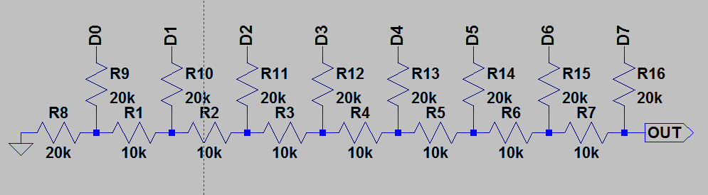
This post is about an R2R Ladder DAC that I build one evening. I wanted to play around with the Arduino Mega 2560 board I have and this seemed like a perfect way to try it out. Below is the schematic for the DAC…
This is an 8-bit DAC built-up from just resistors, each bit is connected to a GPIO pin of the Arduino. I built the circuit on a breadboard and connected it to the Arduino using jumpers.
The first thing I did with the software is toggle the MSB bit using the Ardino digitalWrite() function, however using these functions makes writing to the DAC far too slow. So I needed to write directly to the ATmega GPIO registers and to avoid jitter I use a Timer interrupt. At the moment the software just increments PORTA each interrupt and lets it overflow, this creates a sawtooth wave on the output of the DAC and exercises each bit in the DAC.
When developing software that uses a serial port for communication with the outside world it is really helpful to be able to use a virtual serial port and write test code to aid in debugging. Well it turns out there is a program that does that in Linux, it’s called socat. Using this utility you can create a pair of virtual serial ports and connect them together. To install it in Ubuntu run the following commands.
sudo apt-get update
sudo apt-get install socat
Once you have the socat program installed you just need to run the following command to create a pair of virtual tty devices. When you run the program it will print out which ports you need to use.
socat -d -d PTY,b57600 PTY,link=ttyVS1,b57600
This is an example of the output that socat produces. The two ports it has created are /dev/pts/5 and /dev/pts/6. These can vary from time to time so keep an eye on that.
2013/11/15 07:47:13 socat[2970] N PTY is /dev/pts/5
2013/11/15 07:47:13 socat[2970] N PTY is /dev/pts/6
2013/11/15 07:47:13 socat[2970] N starting data transfer loop with FDs [3,3] and [5,5]
I’m currently working on a project at work that includes a timer that will turn relays on during certain time periods and off outside them. The timer wasn’t nearly as easy as I thought it would be so I decided to prototype the code on the PC as it’s a lot easier to debug than on a tiny little PIC18F. All of the code in this post will be in C# which I what I used to prototype with.
The weird thing about this timer is that the day is assumed change at 3am and not midnight. So a day starts at 3am and ends at 2:59am, this is apparently so that the relay can be on across midnight. This caused massive confusion and I struggled to implement it.
The idea is that the timer will store and work with an internal representation of time and then convert to hours/minutes only when displaying settings to the user and when getting the time from the RTC. This internal representation is a single integer number of minutes from midnight offset in such a way that times less than 03:00am are offset by a day. This means that 03:00am is 180 minutes as you would expect but 02:55 is actually 1615 minutes. Using this representation means that comparing time is really easy and that makes the whole timer and user interface much easier to implement. Below are some constants
const int MinutesPerDay = 1440;
const int MinInternalTime = 180;
const int MaxInternalTime = 1619;
Below is a function that converts hours and minutes to the internal representation. If the time is less than the minimum internal time then it’ll add a whole day to the time.
int TimeToInternal(int hrs, int min)
{
    int time = hrs*60 + min;
    if( time < MinInternalTime) {
        time += MinutesPerDay;
    }
    return time;
}
Next I needed a function to convert the internal representation to actual time, in hours and minutes. Here the time is returned as a tuple of two integers, in the C version I used two pointer parameters instead.
Tuple<int, int> InternalToTime(int time)
{
    if( time > MinutesPerDay ) {
        time -= MinutesPerDay;
    }
    return new Tuple<int, int>(time/60, time%60);
}
I have also implemented a similar timer elsewhere in the project, but it was much simpler and the day changed at midnight as you would expect. This is the code I used to implement the timer that turns on a feature during a time period, then turns off. This period can span across midnight. The time is really simple, just multiply hours by 100 then add the minutes so 11:32 is 1132.
Here is the Period class as I implemented it, nothing special or interesting here
public class Period {
    public Period() {
    }

    public Period(int start, int stop) {
        this.Start = start;
        this.Stop = stop;
    }

    public static int HrsMinToInt(int hrs, int min) {
        return hrs*100 + min;
    }

    public int Start { get; set; }
    public int Stop { get; set; }
}
Sorry if none of this make any sense, this post has mostly just been a brain dump so that if in the future I work on this again, or something similar I can remind myself of all this.
We use cookies on our website to give you the most relevant experience by remembering your preferences and repeat visits. By clicking “Accept All”, you consent to the use of ALL the cookies. However, you may visit "Cookie Settings" to provide a controlled consent.
This website uses cookies to improve your experience while you navigate through the website. Out of these, the cookies that are categorized as necessary are stored on your browser as they are essential for the working of basic functionalities of the website. We also use third-party cookies that help us analyze and understand how you use this website. These cookies will be stored in your browser only with your consent. You also have the option to opt-out of these cookies. But opting out of some of these cookies may affect your browsing experience.
Necessary cookies are absolutely essential for the website to function properly. These cookies ensure basic functionalities and security features of the website, anonymously.
Cookie
Duration
Description
cookielawinfo-checkbox-analytics
11 months
This cookie is set by GDPR Cookie Consent plugin. The cookie is used to store the user consent for the cookies in the category "Analytics".
cookielawinfo-checkbox-functional
11 months
The cookie is set by GDPR cookie consent to record the user consent for the cookies in the category "Functional".
cookielawinfo-checkbox-necessary
11 months
This cookie is set by GDPR Cookie Consent plugin. The cookies is used to store the user consent for the cookies in the category "Necessary".
cookielawinfo-checkbox-others
11 months
This cookie is set by GDPR Cookie Consent plugin. The cookie is used to store the user consent for the cookies in the category "Other.
cookielawinfo-checkbox-performance
11 months
This cookie is set by GDPR Cookie Consent plugin. The cookie is used to store the user consent for the cookies in the category "Performance".
viewed_cookie_policy
11 months
The cookie is set by the GDPR Cookie Consent plugin and is used to store whether or not user has consented to the use of cookies. It does not store any personal data.
Functional cookies help to perform certain functionalities like sharing the content of the website on social media platforms, collect feedbacks, and other third-party features.
Performance cookies are used to understand and analyze the key performance indexes of the website which helps in delivering a better user experience for the visitors.
Analytical cookies are used to understand how visitors interact with the website. These cookies help provide information on metrics the number of visitors, bounce rate, traffic source, etc.
Advertisement cookies are used to provide visitors with relevant ads and marketing campaigns. These cookies track visitors across websites and collect information to provide customized ads.