I created a macro that will generate a really simple Biconvex lens. The macro take in three arguments, Location, Radius and Overlap. It works by taking the intersection of two spheres. The resulting object is then translated to wherever you want it to go in your scene.
I recently brought a USB DVB-T dongle that is based on the Realtek RTL2832U chip which, with RTLSDR, can be used as a really low cost SDR. This is because it can be setup to return the raw I/Q samples to the host PC. Once you have the samples they can then be processed, I tend to use GNURadio for the processing.
There is a script available that downloads and installs everything, RTLSDR, GNURadio, and more. I recomend you try it first. I think there is also a new project from the GNURadio people that will automate building and installing. I had had some issues with building gr-audio when I wrote this so I use the manual method of building the code for now.
Once you have made sure you have all of the libraries that GNURadio needs you can build the code.
mkdir build cd build cmake ../ make && make test
sudo make install
This whole process can take a while to complete. On my work machine it took nearly 40mins! I had an issue building the gr-audio on my laptop that I still haven’t been able to resolve.
Next I built downloaded and extracted the RTLSDR source code. As with GNURadio we need to create a build directory and run cmake.
mkdir build cmake ../ make
Then I ran a few commands to check that the code and the dongle worked correctly. The first tests to make sure samples are being returned at the correct rate and the second will receive and demodulate a WBFM station.
Recently I wondered how you control CPU throttling in GNU/Linux systems so after doing a little research this script is what I’ve come up with. It’s based on some others that I’ve come across. All it does is set the CPU throttling mode to “performance” then displays the current CPU frequency setting, which should be full speed.
#!/bin/sh
for CPUGOV in /sys/devices/system/cpu/cpu*/cpufreq/scaling_governor
do
    echo -n performance > $CPUGOV;
done

# Display Stats about new settings
grep -E '^model name' /proc/cpuinfo | head -n 1
for CPUFREQ in /sys/devices/system/cpu/cpu*/cpufreq/scaling_cur_freq
do
    cat  $CPUFREQ | awk '{ print $1 / 1e6 "GHz"; }'
done

exit 0
I use i3 as my main window manager but I like to play around with others so I know what’s out there. One of the window managers that I find very interesting is dwm. It is a very small window manager, about 2k lines of code and you configure it my changing a header file and re-compiling. Definitely not beginner-friendly!
To make playing easier I wanted to run dwm inside i3, that way I don’t have to keep logging in and out. I could have used a VM but the same problem would exist. Below is the shell script I use to do this. I found out how to do this from LinuxExchange.
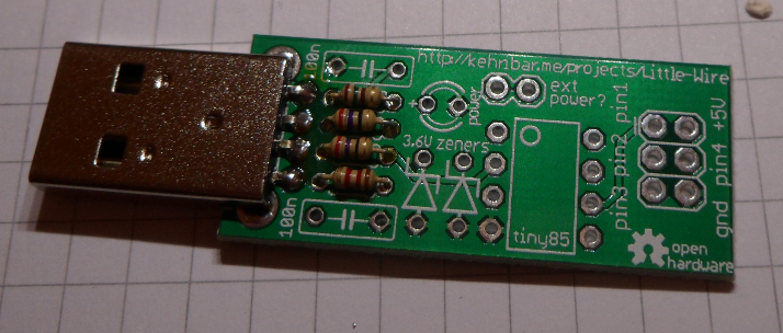
For some reason I need to run dwm twice before it works, the first time it says “dwm: cannot open display”. Anyone know why this is happening? Below is a screenshot of dwm running emacs, it is the bottom right panel. The panel to the left is emacs editing the config.h file.
So far I have modified the background colour of the status bar and set the status message. To set the status message all you need to do is set the WM_NAME property of the root window. Most systems have a utility that lets you do this in the command line.
xsetroot -name “Hello World”
You can also use this utility to change the background colour, I did a similar thing for i3.
There are a lot of different methods used to debounce switch inputs and this post is just about one method that I read about recently and used a couple of times now. So far it seems pretty good and does the job.
The C code for this method is just below, I defined it as a macro so I can use it for multiple switch inputs. All you need to do is execute this code at a fixed sample rate and it will do the rest.
What this basically does is average samples. When the input is high the “integrator” counts up until it reaches the PERIOD constant. Then it sets the output high and also saturates the integrator to the value of PERIOD. When the input is low the integrator counts down until it reaches 0 when it sets the output low.
I cant remember where I found this method, I believe the link is somewhere on Jack Ganssle’s website. He also has a good tutorial on switch debouncing.
This post is a collection of C# method extensions that I have written recently to help me do bit manipulations on unsigned integers. These methods allow you to set, clear, toggle, and write bits. I’ve also added a read method for testing bits.
public static UInt32 SetBit(this UInt32 Value, byte bit)
{
    if (bit >= 32) {
        throw new ArgumentException("bit must be between 0 and 31");
    }

    Value |= (UInt32)(1U << bit);
    return Value;
}

public static UInt32 ClearBit(this UInt32 Value, byte bit)
{
    if (bit >= 32) {
        throw new ArgumentException("bit must be between 0 and 31");
    }

    Value &= ~(UInt32)(1U << bit);
    return Value;
}

public static UInt32 WriteBit(this UInt32 Value, byte bit, bool state)
{
    if (bit >= 32) {
        throw new ArgumentException("bit must be between 0 and 31");
    }

    if (state) {
        Value |= (UInt32)(1U << bit);
    } else {
        Value &= ~(UInt32)(1U << bit);
    }

    return Value;
}

public static UInt32 ToggleBit(this UInt32 Value, byte bit)
{
    if (bit >= 32) {
        throw new ArgumentException("bit must be between 0 and 31");
    }

    if ((Value & (1 << bit)) == (1 << bit)) {
        Value &= ~(UInt32)(1U << bit);
    } else {
        Value |= (UInt32)(1U << bit);
    }

    return Value;
}

public static bool ReadBit(this UInt32 Value, byte bit)
{
    if (bit >= 32) {
        throw new ArgumentException("bit must be between 0 and 31");
    }

    return ((Value & (1 << bit)) == (1 << bit));
}
I also added wrappers so these methods are avaliable UInt16 and Byte types.
Engineers and scientists will often use SI prefixes to make writing down very large, and very small, numbers easier. Writing down 3 GV is much better than 3000000000 V :). I’m currently working on a couple of software projects, both at home and work, where I’d like the ability to enter numbers with SI prefixes for convenience.
First I decided to write down the different styles of input my code will have to support, below is the list of styles I came up with.
+2.2, or -2.2 => I want to be able to specify the sign of a number explicitly
.33333 => I’d like to omit the starting zero
2.2k => Have SI prefixes
2k2 => This style is commonly found in the electronics industry.
Now I know what I want the code to do I can start writing it. I created a dictionary containing the prefixe character and the associated multiplier. I am writing this code in C# by the way, and used LINQPad to try it all out. Once I had it working I put into the class library I was working on.
Then I wrote a method that will take in the input string and convert it to a double. The first thing the method does is check to see if it is a plain number that Double.Parse() can take care of, it does this check using a regex. If the Regex matched then it simply calls the Double.Parse() method and returns the result.
If the regex fails then it check using two more regexes if the number looks like it contains SI prefixes. If it does then we find out what prefix is used then remove the prefix and convert the number.
I am not very good with regular expressions so there may be better ways of writing them than this. I have tested this code quite a bit with different types of input and it seems pretty solid. It will throw a FormatException if anything goes wrong.
// These are the regexes used by the method. These are initialised in a constructor.
Regex plain_number_regex = new Regex(@"^[+-]?(?=[\.\d])\d*(\.\d+)?$"); // For .2222, 0.222, 2.32
Regex si_number_a_regex = new Regex(@"^[+-]?[\d]+[PTGMkcmunpf]?[\d]*$"); // for 2k, 2k2
Regex si_number_b_regex = new Regex(@"^[+-]?[\d]+(\.\d+)?[PTGMkcmunpf]?$"); // For 1.2k

public double ParseInputStringSI(string input)
{
    // Test to see if it is a plain number with no SI prefixes
    if (plain_number_regex.IsMatch(input)) {
        return Double.Parse(input);
    }

    // Test to see if it is a number with an SI prefix.
    if(si_number_a_regex.IsMatch(input) || si_number_b_regex.IsMatch(input) ) {
        // Find where in the string the prefix is and what
        // kind of prefix it is.
        var input_prefix = from p in Prefixes.Keys
                           where input.IndexOf(p) > 0
                           select input[input.IndexOf(p)];

        // Make sure the above query worked. There should be
        // no reason for it to fail because the Regex checks
        // the prefix characters.
        if (input_prefix.Count() == 0) {
            throw new FormatException("Invalid Input");
        }

        // Get the multiplier for the prefix
        var multiplier = Prefixes[input_prefix.First()];

        // Ether replace the prefix with a decimal point or
    // remove it entierly. Depends on the format of the
    // input.
    string inputp;
    if( si_number_a_regex.IsMatch(input) ) {
            inputp = Regex.Replace(input, @"[PTGMkhdcmunpf]", ".");
    } else {
        inputp = Regex.Replace(input, @"[PTGMkhdcmunpf]", "");
    }

        // Attempt the conversion, multiply it then return it.
        var tmp = Double.Parse(inputp);
        return tmp * multiplier;
    } else {
        throw new FormatException("Input String is Invalid");
    }
}
A couple of weeks ago I ordered some stuff from Seedstudio and after a few days they arrived! I brought a Bus Pirate (with some accessories like the LCD adapter) and the Little Wire kit. I will post another article about the Bus Pirate later on, but this post will just be on the Little Wire.
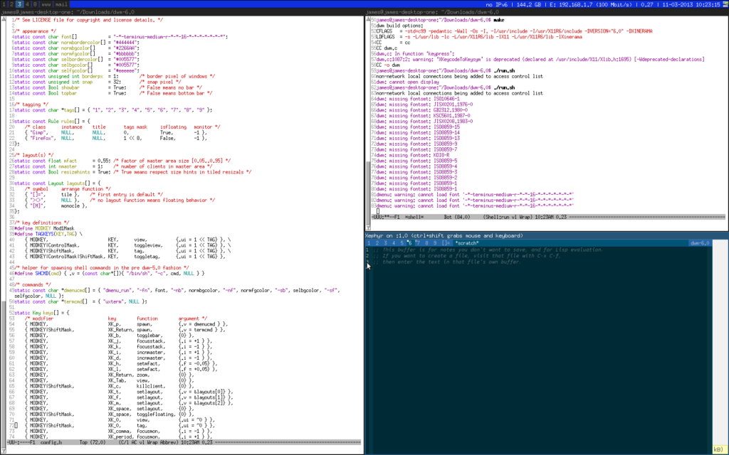
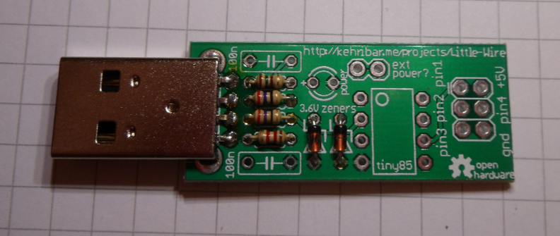
I found out about the Little Wire on Dangerous Prototypes and thought it looked really interesting and I got it while ordering the Bus Pirate. It’s a really tiny through-hole circuit board with an ATTINY85 device, an LED, some passives and a USB A connector. The on-board firmware allows you to control the IO pins of the MCU from a PC. The author of the kit has provided a lot of example software to show you how to use the kit.
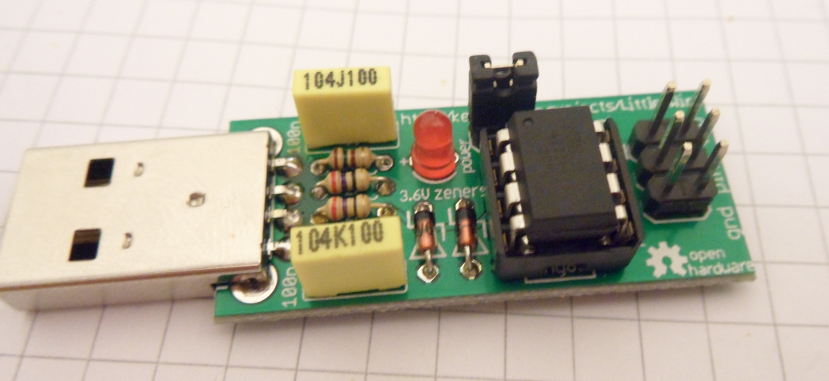
It comes as a kit of parts so it does require assembly, and it is really easy to put together as there are not many parts on it. Below is a photograph of the bare PCB before I started soldering it.
Assembly
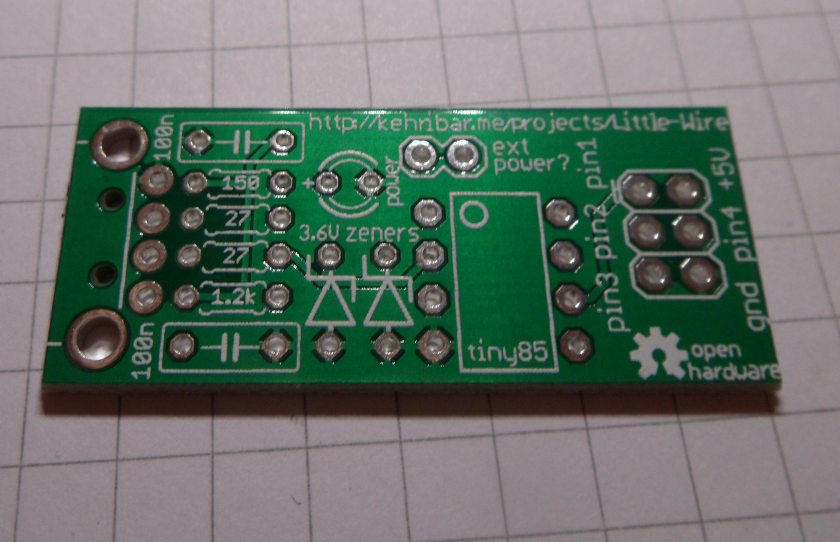
Assembly of the kit is really easy and quick. The first thing I soldered in were the resistors. There are four of them right next to the USB connector.
The next components are the two Zener diodes. These are necessary because the USB data lines D+ and D- are only designed to take 3.3V in and the ATTINY chip is powered by 5V. What the Zeners do is clamp the output of the ATTINY to 3V. Be sure to put them in the correct way around! The black ring signifies the Cathode of the diode.
The next items to go in are the chip socked, capacitors and the pin headers. Unfortunately I didn’t get a photo of these steps, but below is a photo of what the results look like.
Running the Blinky Demo
No that I have the board assembled I want to try it out! I cloned the GitHub repo which has the firmware and a collection of software you can run to interface to the board. Note that I’m using Ubuntu to run the software, your operating system may need different, and/or extra steps.
The C and C++ libraries need libusb installed to compile and use them. If you don’t have libusb installed you can get it with this command
sudo apt-get install libusb-dev
Then you can make the software, in this case I’m running the C example programs. I found out that in I needed to run the example program as root in order for it to work. I am not sure why this is, it may have something to do with how libusb works. The Saleae Logic software also needs to be run as root as well.
make
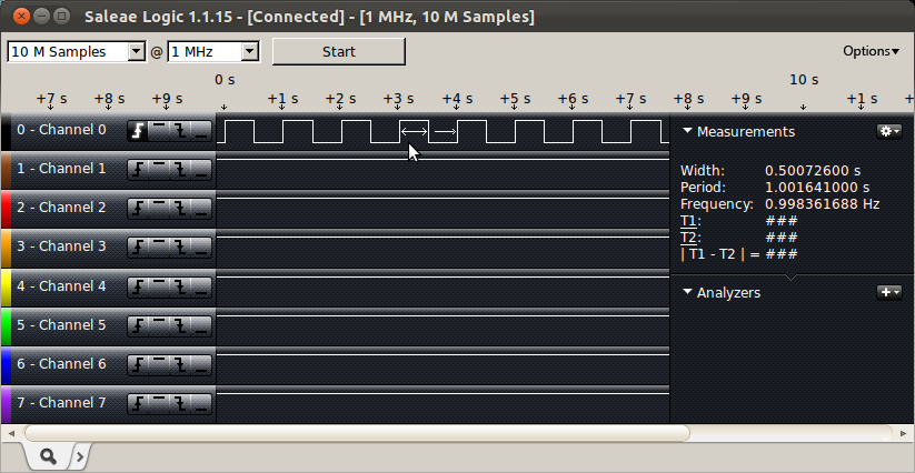
sudo ./blink
Pin 4 of the LittleWire will now be producing a roughly 1Hz square wave. Below is a screen shot of what the Saleae Logic analyser measured on Pin 4.
screenshot of logic analyser output showing the blinking pin
The End….
I’d like to do some more playing around with the Little Wire, I think it will be very useful. I’d like have a go programming an AVR using it. I’d like to play around with the processing code as well. I have also just found out that there is a Basic interpreter written for the Little Wire on GitHub so I think I’ll play around with that bit at some point as well.
It’s really nice to show the user a list of the COM ports they actually have on their machines. All too often I have seen software that makes you type in the COM port name. Even worse are the applications that force you to select from a list of COM ports, usually COM1 to COM5, without the option of typing in a different one!
Below is some really simple code that generates a list of the available COM ports and inserts the list into a drop-down selection control in a WinForms application.
string[] ports = SerialPort.GetPortNames();
if (ports.Length > 0) {
    Array.Sort(ports);
    COMPort.Items.AddRange(ports);
    COMPort.Text = ports[0];
} else {
    COMPort.Text = "Unable to Detect COM ports";
}
When developing embedded firmware I like to define macros that provide aliases for the IO port registers that I need. The name of each of the macros will correspond to the net name on the schematic to make it easy to check for errors. I put all of these macros into a single header file that I can include, I have sometimes seen these called board support packages. They can sometime be entire libraries that abstract details of the hardware. In my case they are just simple header files as that is all I need for now.
Recently I decided to automate some of the work of creating these files as it can be very time consuming. This is the Awk script I ended up with.
#!/usr/bin/awk -f
{
    if ($0 == "") next;

    if ($2 == "PORTA") { port = "A"; }
    if ($2 == "PORTB") { port = "B"; }
    if ($2 == "PORTC") { port = "C"; }
    if ($2 == "PORTD") { port = "D"; }
    if ($2 == "PORTE") { port = "E"; }
    if ($2 == "PORTF") { port = "F"; }
    if ($2 == "PORTG") { port = "G"; }

    print "#define " $1 "_PIN " $3;
    print "#define " $1 "_TRIS TRIS" port "bits.TRIS" port $3;
    print "#define " $1 "_LAT LAT" port "bits.LAT" port $3;
    print "#define " $1 "_PORT PORT" port "bits.R" port $3;
    print "";
}
All I need to do is write a space separated file in which each line contains the name I want, the port it is on and the number of the pin that it is attached to. Then this simple script generates the C code. This was for a PIC24F series micro, I have a slightly different script for a project involving a PIC32 which I may post later.
This makes creating BSP header files really easy, especially if you need to modify the pin assignments!
We use cookies on our website to give you the most relevant experience by remembering your preferences and repeat visits. By clicking “Accept All”, you consent to the use of ALL the cookies. However, you may visit "Cookie Settings" to provide a controlled consent.
This website uses cookies to improve your experience while you navigate through the website. Out of these, the cookies that are categorized as necessary are stored on your browser as they are essential for the working of basic functionalities of the website. We also use third-party cookies that help us analyze and understand how you use this website. These cookies will be stored in your browser only with your consent. You also have the option to opt-out of these cookies. But opting out of some of these cookies may affect your browsing experience.
Necessary cookies are absolutely essential for the website to function properly. These cookies ensure basic functionalities and security features of the website, anonymously.
Cookie
Duration
Description
cookielawinfo-checkbox-analytics
11 months
This cookie is set by GDPR Cookie Consent plugin. The cookie is used to store the user consent for the cookies in the category "Analytics".
cookielawinfo-checkbox-functional
11 months
The cookie is set by GDPR cookie consent to record the user consent for the cookies in the category "Functional".
cookielawinfo-checkbox-necessary
11 months
This cookie is set by GDPR Cookie Consent plugin. The cookies is used to store the user consent for the cookies in the category "Necessary".
cookielawinfo-checkbox-others
11 months
This cookie is set by GDPR Cookie Consent plugin. The cookie is used to store the user consent for the cookies in the category "Other.
cookielawinfo-checkbox-performance
11 months
This cookie is set by GDPR Cookie Consent plugin. The cookie is used to store the user consent for the cookies in the category "Performance".
viewed_cookie_policy
11 months
The cookie is set by the GDPR Cookie Consent plugin and is used to store whether or not user has consented to the use of cookies. It does not store any personal data.
Functional cookies help to perform certain functionalities like sharing the content of the website on social media platforms, collect feedbacks, and other third-party features.
Performance cookies are used to understand and analyze the key performance indexes of the website which helps in delivering a better user experience for the visitors.
Analytical cookies are used to understand how visitors interact with the website. These cookies help provide information on metrics the number of visitors, bounce rate, traffic source, etc.
Advertisement cookies are used to provide visitors with relevant ads and marketing campaigns. These cookies track visitors across websites and collect information to provide customized ads.